

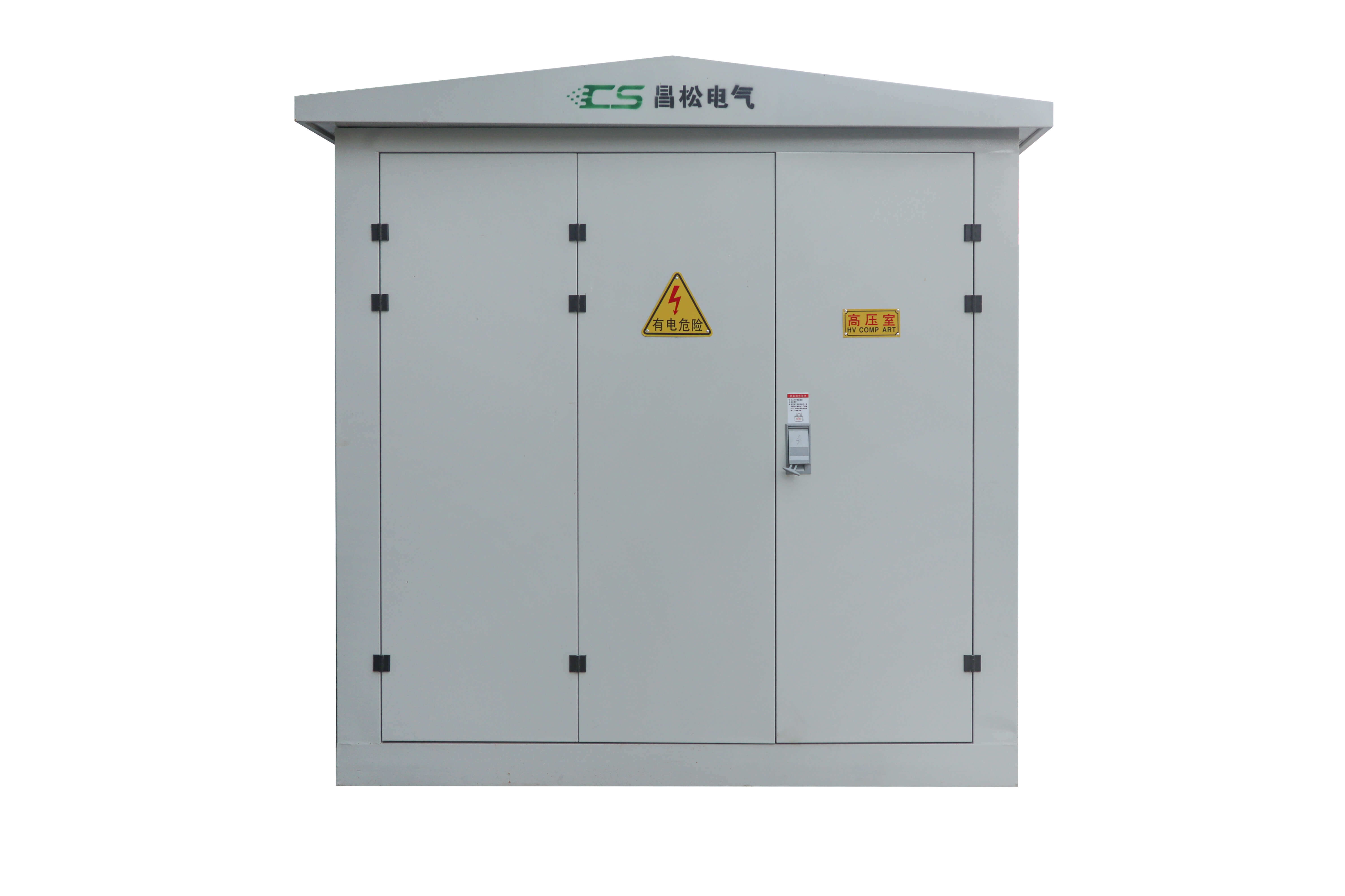
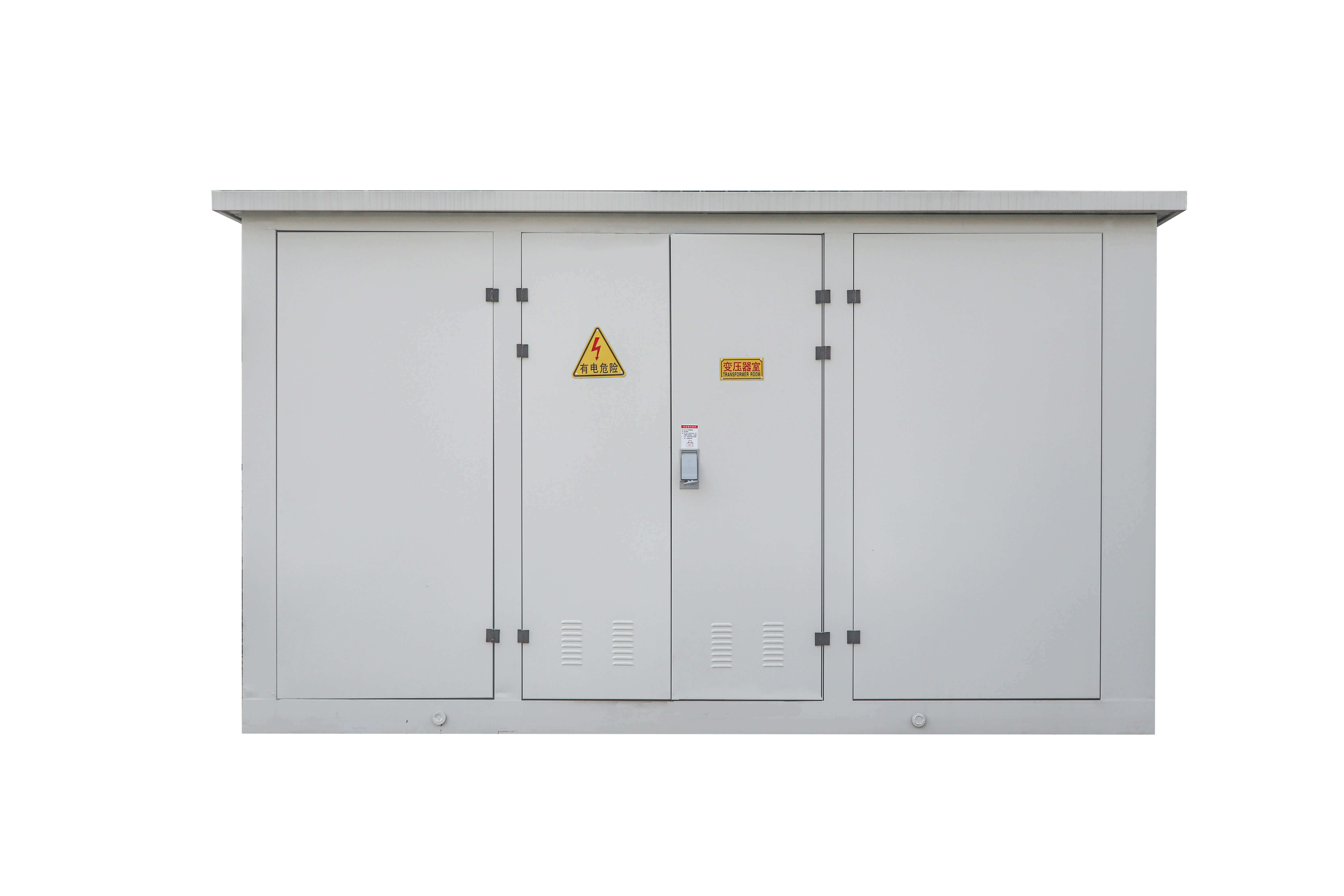
Photovoltaic boost substation
- Product Description
- Wind-integrated ceilingAn integrated ceiling structure is adopted to enhance overall aesthetics and product grade, while optimizing ventilation paths to improve heat dissipation efficiency.
- Integrated air duct designBy adopting a modular air duct layout, ventilation volume is increased, the operating temperature of the inverter is reduced, and equipment safety and power generation efficiency are ensured.
- Integrated cabinet structureThe boost module and power distribution unit are deeply integrated with the cabinet, reducing space occupation and enhancing both aesthetic appeal and structural strength.
- Spatial layoutPlan the space inside the box scientifically, reserve sufficient maintenance passages to facilitate later-stage maintenance and component replacement.
- The product consists of three parts: a low-voltage incoming cabinet, a dual-split transformer, and a high-voltage outgoing cabinet, adopting a "grid"-shaped compartment layout to achieve electrical isolation and functional zoning.
- The low-voltage chamber is equipped with telecontrol devices and power transformers, enabling remote monitoring of the box-type substation and self-power supply, thereby enhancing intelligent management.
- The enclosure is made of stainless steel/aluminum, featuring excellent corrosion resistance and adapting to harsh environments such as coastal salt spray and desert sandstorms.
- The sealed structural design effectively blocks dust and moisture, ensuring the long-term stable operation of the equipment in humid or dusty environments.
- Medium-voltage distribution network (10 kV): suitable for small-scale distributed projects or short-distance power transmission;
- High-voltage power distribution network (35 kV): Suitable for large centralized power stations or long-distance power transmission.
- Insulation strength: upgraded in accordance with GB/T 11022 standard;
- Temperature rise correction: For every 1000-meter increase in altitude, the temperature rise limit decreases by 3 to 5 K;
- Thermal dissipation design: Enhanced ventilation or liquid cooling technology.
- Box material: 316L stainless steel or anodized aluminum is selected;
- Anti-corrosion coating: Spraying epoxy zinc-rich primer + polyurethane topcoat;
- Sealed structure: Adopts double-layer sealed doors + waterproof breath valve.
- Foundation levelness: error ≤ 5 mm/m;
- Grounding resistance: measured value ≤ design value;
- Cable sealing: Waterproof plugs + sealant are used for incoming and outgoing wire holes;
- Functional testing: remote communication, protection action, temperature rise control, etc.
- Daily: Inspect the appearance of the box and the operation indicator light;
- Weekly: Clean the dust from the vents;
- Monthly: Test grounding resistance and non-electrical quantity protection devices;
- Annually: Conduct preventive tests (insulation resistance, DC resistance, etc.).
Product Overview
Photovoltaic step-up substations, also known as photovoltaic step-up box-type substations or photovoltaic combined transformers, are core equipment in photovoltaic power generation systems for stepping up low-voltage electrical energy to enable grid connection. In large-scale photovoltaic power plants, the direct current generated by photovoltaic modules is converted into alternating current by inverters, with the voltage typically ranging from 0.315 kV to 1 kV, which is far below the grid connection standards of 10 kV or 35 kV. By integrating step-up transformers, high-voltage switchgear, low-voltage distribution equipment, and auxiliary systems, photovoltaic step-up substations elevate the low-voltage electrical energy output by inverters to the target voltage level, enabling long-distance transmission and grid connection of electrical energy. Designed and manufactured in strict compliance with national standards such as GB/T 17467 "High-voltage/Low-voltage Prefabricated Substations," these products feature a prefabricated, complete-set structure with high protection, intelligence, and environmental adaptability, and are widely used in centralized photovoltaic power plants, distributed photovoltaic projects, and photovoltaic-storage integrated systems.
Main product features
1. Structural optimization design
2. Functional Modular Integration
3. Enhanced environmental adaptability
Detailed product parameters
| Parameter category | Specific parameters |
|---|---|
| Brand | Changsong Electric |
| Place of origin | Made in China |
| Product model | Changsong PV-XX (XX represents capacity specification) |
| Functional orientation | Boosting and grid connection of photovoltaic power |
| Input voltage range | 0.315 kV ~ 1 kV (AC) |
| Output voltage level | 10kV/35kV (customizable according to requirements) |
| Capacity configuration | Single unit supports 3~5 MW photovoltaic access (conventional project) |
| Material | Box body: Stainless steel/aluminum; Internal components: High-conductivity copper material, insulating silicon steel sheets |
| Protection grade | IP54 (default), can be upgraded to IP65 according to the environment |
| Corrosion resistance grade | C4 (coastal environment), C3 (inland environment) |
| Cooling method | Natural air cooling + forced air cooling (intelligent temperature control switching) |
| Intelligent functions | Remote control, self-power supply, non-electrical quantity protection monitoring (oil level, gas, pressure) |
| Installation method | Ground foundation installation with an inclination ≤3° |
| Grounding requirements | Grounding resistance ≤ 4 Ω (complying with GB/T 50065 standard) |
Scope of application
1. Centralized ground-mounted photovoltaic power station
In large-scale photovoltaic (PV) bases located in northwestern deserts, mountainous areas, and Gobi regions, serving as the step-up nodes between the PV array areas and the collection lines, they elevate the low-voltage electrical energy output from each PV array unit to 10 kV or 35 kV, which is then transmitted through collection lines to the main transformers in the step-up substation, enabling large-scale grid integration of electrical energy.
2. Distributed industrial and commercial photovoltaic projects
It is applicable to scenarios such as industrial parks, logistics parks, and commercial building rooftops, enabling direct connection to medium- and low-voltage distribution networks after local voltage conversion, supporting the "self-generation for self-consumption with surplus electricity fed into the grid" model, and reducing corporate electricity costs.
3. Fisheries-solar and Agriculture-solar Complementary Projects
With excellent corrosion resistance and sealing performance, it can be deployed in humid or dusty environments such as floating photovoltaic systems and agricultural greenhouses, ensuring long-term stable operation of equipment under harsh conditions while also taking into account the efficiency of comprehensive land utilization.
4. Photovoltaic-energy storage integrated system
It works in coordination with the energy storage converter to achieve voltage matching during the charging and discharging processes, supports the joint scheduling of photovoltaic power generation and energy storage systems, and enhances grid flexibility and renewable energy consumption capacity.
Frequently Asked Questions (FAQ)
Q1: How to select the capacity of a photovoltaic step-up substation?
A: It needs to be determined based on the total installed capacity of the project. For conventional projects, the planning can be based on each box-type substation connecting to a photovoltaic capacity of 3 to 5 MW. For example, it is recommended to configure 2 to 3 Changsong PV-XX type booster substations for a 10 MW photovoltaic power station.
Q2: How is the output voltage level determined?
A: Selection shall be made in combination with local power grid access requirements:
Q3: What should be noted when using it in high-altitude areas?
A: When the altitude exceeds 2,000 meters, plateau-type equipment should be selected, and the following parameters should be confirmed:
Q4: How to prevent corrosion in coastal salt spray environments?
A: It is recommended to take the following measures:
Q5: How to conduct acceptance inspection after installation?
A: The following items need to be inspected:
Q6: What is the frequency of routine maintenance?
A: It is recommended to implement according to the following cycle: